


![]() Please call us ! 📞
Please call us ! 📞
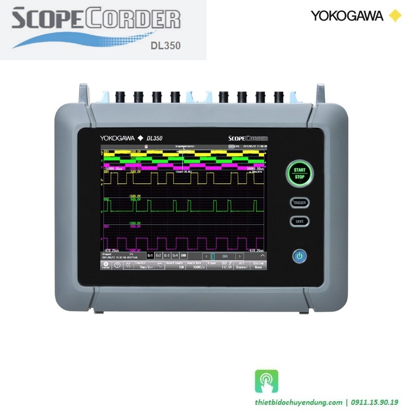
![]() DL350 Portable ScopeCorder at a time to capture up to 32 channels plus 16 built-in channels of digital input.
DL350 Portable ScopeCorder at a time to capture up to 32 channels plus 16 built-in channels of digital input.
![]() Flexible and swappable input modules with built-in signal conditioning
Flexible and swappable input modules with built-in signal conditioning
![]() Input types include: #Voltage & Currents #Temperature #Vibration Acceleration #Strain #Frequency
Input types include: #Voltage & Currents #Temperature #Vibration Acceleration #Strain #Frequency
![]() Logic Signals & CAN #CAN FD #LIN and SENT #Sensor Outputs
Logic Signals & CAN #CAN FD #LIN and SENT #Sensor Outputs
![]() Use it like a data acquisition system or a long memory oscilloscope
Use it like a data acquisition system or a long memory oscilloscope
![]() Verify power line quality using harmonic, power or FFT analysis
Verify power line quality using harmonic, power or FFT analysis

Hotline: 0911.159.019

Email: sales@thietbidochuyendung.com
The DL350 Portable ScopeCorder combines all the measurement and recording capabilities you need when you are away from your office or lab - all in one compact instrument
|
Featuring a resistive touch screen, the DL350 provides the flexibility you need when you need it. Whether you are recording high-speed transients or long-term signals, using “quick and simple” setup or advanced features, the DL350 makes complete measurements completely portable.
Application Notes
|
Portability
Mobility
|
Modularity
|
|---|
|
Choose from 20 types of input modules and install up to 2 in the DL350 Portable ScopeCorder at a time to capture up to 32 channels plus 16 built-in channels of digital input. Input types include: Voltage & Currents Sensor Outputs Temperature, Vibration/Acceleration, Strain, Frequency Logic Signals & CAN / CAN FD / LIN and SENT
Up to 20G points* of data per module can be recorded directly to an SD card. This means that the DL350 can be used for continuous recording for up to 50 days. For high speed signals, up to 100 M points per module of internal memory is available to capture fast transients. This is up to 10,000 times more than other portable oscilloscopes or test tools and thus signals can be captured with higher sample rates or for much longer periods
The power in single- and 3-phase systems can be evaluated. Additionally for fundamental waveforms of 50 or 60 Hz, up to 40 harmonic orders can be analyzed. Alternatively use the suite of FFT functions to perform full frequency analysis. |
Vibration resistant: Instruments used for in-vehicle driving tests or field maintenance must be able to make reliable measurements. The DL350 has an aluminum inner frame and an external rubber bumper and conforms to the Japanese JIS D1601 standard for resisting in-vehicle shock and vibration.Wide Temperature Range: Even when used with the rechargeable battery, the DL350 will operate in temperatures from 0 to 45 degrees. The DL350 brings high-quality laboratory measurements into the harsh environments of the field.
The user has a choice of a simple level trigger or can use enhanced triggers such as pulse width, waveform period and triggers across multiple channels. For example, the wave window trigger is ideal for AC power line monitoring which enables voltage sags, surges, spikes, phase shifts or drop outs to be easily captured (available for 40 to 1,000 Hz waveforms). Leave a DL350 unattended and automatically save the waveform to a file or send a notification email if and when it triggers. |
|---|
| . | |
|---|---|
|
Type |
Plug-in Input Unit |
|
Number of Slots |
2 |
|
Maximum number of input channels |
|
|
Memory Capacity |
Total 200 Mpoint (100 Mpoint per Module) |
|
Display |
|
|---|---|
|
Main Unit Standard Logic Input |
|
|
Data Storage |
|
|
Ethernet |
Conector type: RJ-45 modular jack Communication protocol TCP/IP Supported services DHCP, DNS, SNTP client, SMTP client, FTP client, VXI-11, and Web server |
|
Power Supply |
|
| Recorder Mode Function | |
|---|---|
|
Recording Coditions |
|
|
Acquisition Mode |
|
|
Recording time |
A10 seconds to 50 days |
|
Sampling Interval |
1 µs to 200 ms (1-2-5 system) |
|
Action when recording is finished |
Saves display image data, saves waveform data, sounds a notification buzzer and transfers an e-mail. |
|---|---|
|
Real-time SD card recording |
Binary Format
ASCII Format
|
|
Event Recording |
Able to record up to 100 events through the event input terminal |
|
Display time length |
|
|
Maximum number of displayed traces |
32 (standard logic: 16 bit, including Math) |
| Scope Mode Function | |
|---|---|
|
Acquisition mode |
|
|
Record length |
10 k, 25 k, 50 k, 100 k, 250 k, 500 k, 1 M, 2.5 M, 5 M, 10 M, 25 M, 50 M, 100 M (points) |
|
Selectable time scale range |
|
|
Action when recording is finished |
Saves display image data, saves waveform data, sounds a notification buzzer and transfers an e-mai |
|
Real-time SD card recording (binary format) |
|
|---|---|
|
Event Recording |
Able to record up to 100 events through the event input terminal |
|
Maximum number of displayed traces |
32 (standard logic: 16 bit, including Math) |
|
History Feature |
Up to 1000 histories |
|
Accumulation |
Waveform overlay (The number of times is limitless.) |
Specification | Brochure | Manual Instruction
[Hotline | 0911.159.019] |

 DL350 Portable ScopeCorder at a time to capture up to 32 channels plus 16 built-in channels of digital input.
Flexible and swappable input modules with built-in signal conditioning
Input types include: #Voltage & Currents #Temperature #Vibration Acceleration #Strain #Frequency
Logic Signals & CAN #CAN FD #LIN and SENT #Sensor Outputs
Use it like a data acquisition system or a long memory oscilloscope
Verify power line quality using harmonic, power or FFT analysis